The big difference of those two is that Stantum manufactures multi-touch touch screens while Touchco offers opaque but flexible pressure sensitive multi-touch pads.
This post will illustrate how the Stantum's touch screen works with your fingers.
Mechanical Structure
It has two ITO (Indium Tin Oxide) patterned plates separated by spacing dots. The top layer has ITO columns and bottom layer has ITO rows.
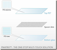
In US 2007/0198926 A1, the PMatrix configuration is described in more detail. Unlike the above PMatrix illustration, the patent says that column lines are located at the bottom layer. In the remaining part of this post, I’ll take the figure of the patent as a reference configuration.
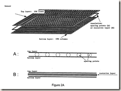
Sensing Single Touch
Let us first consider the case of single-touch. 5V is applied to a column, and a voltage measurement circuit is attached to a horizontal sensing line. Other columns and sensing lines are set to high impedance and ground potential, respectively:
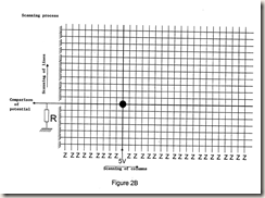
When there is no touch, the measured voltage is zero since current does not go to the measurement circuit. When there is touch, the column and the sensing line are electrically connected and the measurement circuit detects an electrical potential. Therefore, the touch can be determined by simply checking the measured voltage. If it is 0, there is no touch. Otherwise, a user touches the point. Practically this decision is done by a voltage comparator – thresholding.
Sensing Multi-Touch
An example of multi-touch is shown below. There are five touch points. A column and a sensing line crossing the contact point 0 are currently selected:
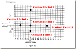
In order to identify multiple touch points, I think that the sensing circuit need to be slightly modified. In the above configuration, inactive sensing lines are grounded. So, the contact point 1 will mask contact point 0 since the current from the 5V source directly goes to the corresponding grounded sensing line.
To avoid the masking problem, the electronic schematic should be changed so that all inactive sensing lines are set to high-impedance. You can find the modified schematic at Tekscan.
Resistance of ITO
The columns and lines are made from ITO whose electrical resistance is quite high. The patent addresses two problems due to the high resistance:
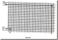
“In fact, the resistance of the transparent material (ITO) composing the columns and the lines increases proportionately to the length of the tracks. Thus, the potential measured at the lower left corner of the sensor will be greater than the potential measured at the upper right corner.”

”In FIGS. 2E and 2F, the cloud of points absorbs a large part of the electrical potential of the fed column. The potential measured at the isolated point is therefore too low to be detected.”
The solution for the problems is to assign different thresholds for each column and line:
“A solution to this problem is in using a voltage comparator piloted digitally at the output of the line to determine whether the tension observed is sufficient for being considered as resulting from the action of a finger on the tactile tile. The reference value of the comparator (comparison threshold) is decremented at each line measure. Thus, the comparison values of the last lines are lower than those of the first lines, which allows the contact point located at the lower left or the upper right to be detected in the same manner.”
Data Processing
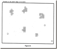
The multi-touch sensing hardware gives the following two-dimensional touch data:
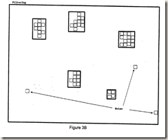
The data processing algorithm identifies valid touch regions and remove noisy elements:
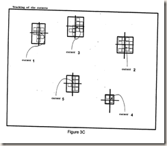
Center points are calculated for all touched regions. Those points are what the touch screen delivers to host applications.
Updated Dec. 9, 2009
- See also: Stantum's WO Patents

1 comment:
Another User Interface for multi touch could be http://www.youtube.com/watch?v=te9O8HavQpQ
Post a Comment